Welcome to our new forum
All users of the legacy CODESYS Forums, please create a new account at account.codesys.com. But make sure to use the same E-Mail address as in the old Forum. Then your posts will be matched.
Close
I am a new user here and I have a raspberry Pi 3 model B which I have installed CODESYS Control for Raspberry Pi MC SL. I am trying to communicate with the MCP23017 chip using i2c. I have downloaded the library, and driver as well as the sample code but I am not able to get it to work - thus any help would be greatly appreciated.
I have managed to communicate with the MCP23017 chip using the raspberry pi terminal itself using the code
$ i2cset -y 1 0x20 0x00 0x00 (this code on the pi declares all pins of Bank A (GPA) as outputs)
$ i2cset -y 1 0x20 0x14 0x01 (this code on the pi turns on the 1st led on channel A)
I have been trying to replicate this in codesys but its not working and I am quite lost. If anyone has some tips please contact me.
Kind regards, Oliver
If you would like to refer to this comment somewhere else in this project, copy and paste the following link:
Anonymous
-
2019-12-21
Originally created by: phenixrb
hello oliver,
Codesys does not manage MCP23017 in I2C, but MCP23S17 in SPI.
Sorry for my late response - hope you all had a lovely Christmas.
Yes I downloaded that driver, library and sample code from that thread Edwin but I was not able to get any response. I think I am missing something trivial but such as setting the GPIO to an input/output but I am not able to see the i2c gpio in codesys. Is this correct?
If anyone has 30 minutes (or any time at all) to have a quick run through of what I have already done and give some advice I would greatly appreciate it.
I look forward to hearing from you
If you would like to refer to this comment somewhere else in this project, copy and paste the following link:
Hello
from time to time I trying to work with the MCP23017. I have no problem to use the MCP ports as inputs but until now I was not able to use the MCP ports as outputs (e.g. to control a LED).
Regards
JJoe
If you would like to refer to this comment somewhere else in this project, copy and paste the following link:
Sorry I forgot my Codesys code:
MCP23017_0x24.OUT_A:=16#00; //Porta --> Output
MCP23017_0x24.OUT_B:=16#FF; //PortB --> Input
GVL.xPB:=MCP23017_0x24.IN_B.0;
IF NOT GVL.xPB THEN
MCP23017_0x24.OUT_A.0:=TRUE;
MCP23017_0x24.OUT_A.1:=TRUE;
MCP23017_0x24.OUT_A.2:=TRUE;
MCP23017_0x24.OUT_A.3:=TRUE;
MCP23017_0x24.OUT_A.4:=TRUE;
MCP23017_0x24.OUT_A.5:=TRUE;
MCP23017_0x24.OUT_A.6:=TRUE;
MCP23017_0x24.OUT_A.7:=TRUE;
END_IF
IF GVL.xPB THEN
MCP23017_0x24.OUT_A.0:=FALSE;
MCP23017_0x24.OUT_A.1:=FALSE;
MCP23017_0x24.OUT_A.2:=FALSE;
MCP23017_0x24.OUT_A.3:=FALSE;
MCP23017_0x24.OUT_A.4:=FALSE;
MCP23017_0x24.OUT_A.5:=FALSE;
MCP23017_0x24.OUT_A.6:=FALSE;
MCP23017_0x24.OUT_A.7:=FALSE;
END_IF
If you would like to refer to this comment somewhere else in this project, copy and paste the following link:
I have used this library and this example to use the MCP23017 as digital outputs, but there is no change on IO pins when I change the state (always 5V on pins).
Why is there no change on pins?
Regards
If you would like to refer to this comment somewhere else in this project, copy and paste the following link:
Because there is something wrong with the initalization andthe preconfigured values (inputs) from the library are used.
I found solutions for the issue "not being able to change the outputs, before a dump via linux shell":
quick and dirty: change the preconfigured value in the library for your needs. Use 16#FF for Inputs and 16#00 for outputs:
IO_A:BYTE:=16#FF;IO_B:BYTE:=16#FF;
more usually one: reinitialize the port configuration on request. Add this code in the library to the case structure in the FB:
10:IFREINITTHEN_iState:=0;END_IF
Additionally you have to trigger/request the reinitialization of the configuration after the device is "operational". And if you want to you can change the polarity and wether the Port A/B is configured as input or output during runtime. Add this code or parts of it to your project:
Declaration:
IPOL_A:BYTE:=16#00;// Port A configuration: 0=same/1=opposite (INPUT POLARITY PORT REGISTER)IPOL_B:BYTE:=16#00;// Port B configuration: 0=same/1=opposite (INPUT POLARITY PORT REGISTER)
Code:
STATE := STATE AND write8(16#02,IPOL_A); // IPOL: INPUT POLARITY PORT REGISTER // 1=GPIO register bit reflects the opposite logic state of the input pin. // 0=GPIO register bit reflects the same logic state of the input pin.STATE := STATE AND write8(16#03,IPOL_B); // IPOL: INPUT POLARITY PORT REGISTER // 1=GPIO register bit reflects the opposite logic state of the input pin. // 0=GPIO register bit reflects the same logic state of the input pin.
Hello Everyone,
I am a new user here and I have a raspberry Pi 3 model B which I have installed CODESYS Control for Raspberry Pi MC SL. I am trying to communicate with the MCP23017 chip using i2c. I have downloaded the library, and driver as well as the sample code but I am not able to get it to work - thus any help would be greatly appreciated.
I have managed to communicate with the MCP23017 chip using the raspberry pi terminal itself using the code
$ i2cset -y 1 0x20 0x00 0x00 (this code on the pi declares all pins of Bank A (GPA) as outputs)
$ i2cset -y 1 0x20 0x14 0x01 (this code on the pi turns on the 1st led on channel A)
I have been trying to replicate this in codesys but its not working and I am quite lost. If anyone has some tips please contact me.
Kind regards, Oliver
Originally created by: phenixrb
hello oliver,
Codesys does not manage MCP23017 in I2C, but MCP23S17 in SPI.
l viewtopic.php?f=23&t=6247 l
Hello, in my brief search I couldn't find your exact Codesys driver.
You can make your own though, here is the documentation.
https://forge.codesys.com/drv/io-drivers/doc/I2C/
If you decide to develop your driver on forge.codesys.com, there is a wonderful community to help when you are stuck.
Let me know if there are any specific questions about the process, or of course you can ask there.
Hi,
you could give the driver from the section here a try:
l viewtopic.php?f=23&t=5872 l
or is it what you have already done?
This section will move to forge too...next
BR
Edwin
Hello everyone,
Sorry for my late response - hope you all had a lovely Christmas.
Yes I downloaded that driver, library and sample code from that thread Edwin but I was not able to get any response. I think I am missing something trivial but such as setting the GPIO to an input/output but I am not able to see the i2c gpio in codesys. Is this correct?
If anyone has 30 minutes (or any time at all) to have a quick run through of what I have already done and give some advice I would greatly appreciate it.
I look forward to hearing from you
Hi,
no mapping is needed for I2C on the GPIO's.
Did you enable I2C by using CLI?
sudo raspi-config
That's basically the only thing which is needed.
You could check your device by:
i2cdetect -y 1
0 1 2 3 4 5 6 7 8 9 a b c d e f
00: -- -- -- -- -- -- -- -- -- -- -- -- --
10: -- -- -- -- -- -- -- -- -- -- -- -- -- -- -- --
20: -- -- -- -- -- -- -- -- -- -- -- -- -- -- -- --
30: -- -- -- -- -- -- -- -- -- -- -- -- -- -- -- --
40: -- -- -- -- -- -- -- -- -- -- -- -- -- -- -- --
50: -- -- -- -- -- -- -- -- -- -- -- -- -- -- -- --
60: -- -- -- -- -- -- -- -- -- -- -- -- -- -- -- --
70: -- -- -- -- -- -- -- --
If this works CODESYS should work with the I2C too.
BR
Edwin
Hello
from time to time I trying to work with the MCP23017. I have no problem to use the MCP ports as inputs but until now I was not able to use the MCP ports as outputs (e.g. to control a LED).
Regards
JJoe
Sorry I forgot my Codesys code:
MCP23017_0x24.OUT_A:=16#00; //Porta --> Output
MCP23017_0x24.OUT_B:=16#FF; //PortB --> Input
GVL.xPB:=MCP23017_0x24.IN_B.0;
IF NOT GVL.xPB THEN
MCP23017_0x24.OUT_A.0:=TRUE;
MCP23017_0x24.OUT_A.1:=TRUE;
MCP23017_0x24.OUT_A.2:=TRUE;
MCP23017_0x24.OUT_A.3:=TRUE;
MCP23017_0x24.OUT_A.4:=TRUE;
MCP23017_0x24.OUT_A.5:=TRUE;
MCP23017_0x24.OUT_A.6:=TRUE;
MCP23017_0x24.OUT_A.7:=TRUE;
END_IF
IF GVL.xPB THEN
MCP23017_0x24.OUT_A.0:=FALSE;
MCP23017_0x24.OUT_A.1:=FALSE;
MCP23017_0x24.OUT_A.2:=FALSE;
MCP23017_0x24.OUT_A.3:=FALSE;
MCP23017_0x24.OUT_A.4:=FALSE;
MCP23017_0x24.OUT_A.5:=FALSE;
MCP23017_0x24.OUT_A.6:=FALSE;
MCP23017_0x24.OUT_A.7:=FALSE;
END_IF
Hello,
I have used this library and this example to use the MCP23017 as digital outputs, but there is no change on IO pins when I change the state (always 5V on pins).
Why is there no change on pins?
Regards
Because there is something wrong with the initalization andthe preconfigured values (inputs) from the library are used.
I found solutions for the issue "not being able to change the outputs, before a dump via linux shell":
Additionally you have to trigger/request the reinitialization of the configuration after the device is "operational". And if you want to you can change the polarity and wether the Port A/B is configured as input or output during runtime. Add this code or parts of it to your project:
Declaration:
Code:
I tested this positively with the old library (posted from eschwellinger at 2021-11-27 https://forge.codesys.com/forge/talk/Runtime/thread/8981ce928a/?page=1&limit=25#1cc1) and with the new library (posted from elconfa at 2019-01-10 https://forge.codesys.com/forge/talk/Runtime/thread/a2dd4dd45f/#774c). Finally, I extended the new library so that the polarity switching of the inputs can be controlled with a variable:
Declaration:
Code:
Nice job, What am I doing wrong here? I added the device and library. When adding the module it says the following.
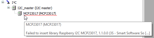
Last edit: rubendijk 2023-04-04