Home
Hardware
This driver supports an A/D converter from Microchip technology inc. It is an SPI device, which features 4 or 8 analog channels, which are autonomously sampling the signals at a pretty high rate:
- 75ksps at 2.7V
- 200ksps at 5V
This is far beyond what we are able to read via Linux over SPI.

Prerequisites
You need to have the device description and driver library installed from the "MCP3008" project.
Usage
This driver can be used in a similar way as most other CODESYS devices. You add it to your project and map your input variables.
Wiring
The chip has to be connected to a free SPI port. We assume, that you connect the chip with a chip select that coresponds to your SPI port. ATM we don't support to use general GPIOs for chip selects. Also no daisy chaining is supported, as the device doesn't support that.
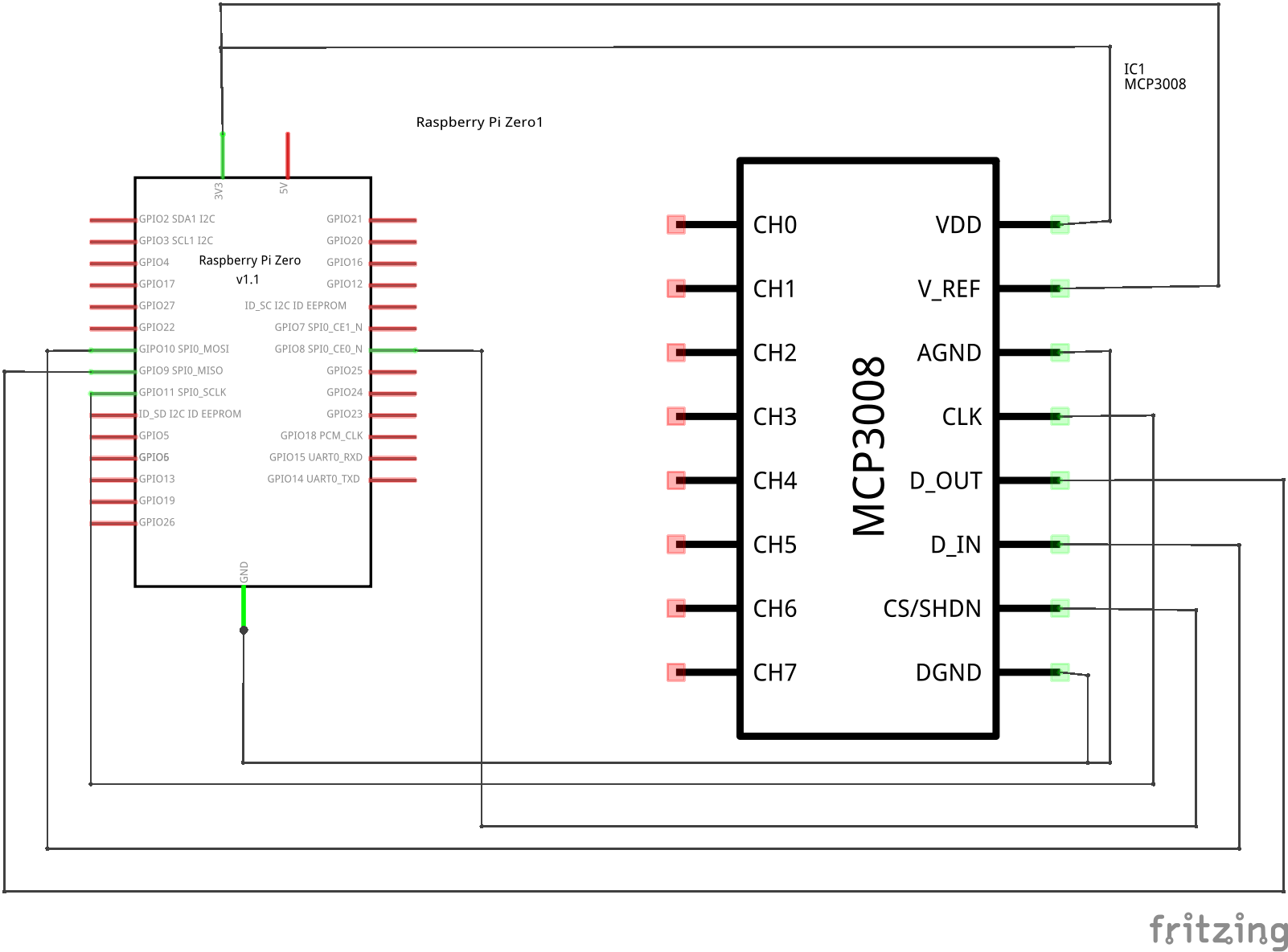
This example shows the wiring of an MCP3008 with a Raspberry Pi on SPI port 0 and chip select 0. This corresponds to "spidev0.0".


Add the device
The device is named MCP3008 and has to be inserted below an SPI Master of your CODESYS project.
- Right click on SPI master
- Add Device
- Select the MCP3008
Configure the SPI port
The SPI port and chip select have to be set to the Pins, where you connected the MCP3008.
- Double Click on the SPI Master
- Set the configuration parameters
The first number specifies the SPI bus. The second number specifies the chip select.
Use the A/D values
You can easily map the analog input channels to some variables within your project.
- Just create a variable of type DWORD,
- go to the "I/O Mapping" page of the MCP3008 device,
- double click on your desired I/O channel,
- and click on the button "..." to select your variable.