Driver FB
-
Driver Documentation
-
Database
I/O driver
An I/O driver in the world of CODESYS is a piece of software, that abstracts the access to a piece of hardware, which usually provides input data (like temperatures, switches, ...) or drives outputs (analog, digital, PWM, ...).
The way to use those I/Os is usually, to add the modules to the device tree of your CODESYS project, configure them and map the input and output channels to variables i your application.
Function Block
When start writing an I/O driver in IEC, the best way is to start with a function block. The reason is, that it is very easy to pass the input and output values of your hardware to the inputs and outputs of your FB.
Try to keep the interface of the FB as simple as possible, and do all the work, which is necessary to handle the hardware in the main POU of the FB.
So if you for example read a value of a sensor through SPI, name the input of the FB accordingly, and code the SPI access inside of your FB.
I/O driver interface
When you have such an FB, it becomes very straight forward to write an I/O driver frame around that, so that the user can easily add this driver to his project, like he is used to do it with other fieldbusses in CODESYS.
Device Description
A device description is an XML file, which describes the I/O module, so that the user can add it to the device tree in CODESYS. It mainly consists of configuration parameters and I/O channels.
<!-- Configuration parameter -->
        <Parameter ...>
          <Attributes channel="none" ... />
          ...
        </Parameter>
<!-- Input channel -->
        <Parameter ...>
          <Attributes channel="input" ... />
          ...
        </Parameter>
<!-- Output Channel -->
        <Parameter ...>
          <Attributes channel="output" ... />
          ...
        </Parameter>
The purpose of those kinds of parameters is easily explained:
- Configuration Parameters can be used to configure things at compile time (e.g. baudrate, frequency, ...).
- Input Channels can be used to map an input (e.g. position od rotary encoder, temperarure, ...) to a variable of the application.
- Ourput Channels can be uses to map an output (e.g. relais output, PWM, ...)to a variable of the application.
When you hit "add device" in CODESYS, you get only a list of devices, which are allowed under the selected device. To let CODESYS know which devices are allowed, we have to define so called connectors with interfaces.
<Connector interface="OpenSource:Internal" ...>
The algorithm is simple - you have parent and child connectors, each with 1-n interfaces. Each combination of parent and child, where at least one of the interface names matches is valid, and therefore displayed in the "add device" dialog of CODESYS.
Install the device description
To make your device known to CODESYS, you need to install it to the device repository (Tools -> Device Repository -> install). During development, you will most likely need to install your device descriptions several times for tests. After you installed a new version, it is important to right click on existing devices in your project and select "update device".
Mapping the I/Os
If you wrote a correct device description, and installed it, you should now be able to map your I/Os to variables of your application. After you downloaded such a driver, you get a call to the function IoDrvUpdateConfiguration. This is your chance to parse the I/O configuration, initialize the hardware and prepare your internal data structures, so that you can efficiently copy the I/O data from and to the hardware.
As we decided to use an FB interface to implement our driver, we keep it simple and store a pointer to the input and output variables of our FB.
    //Setup I/O area
    FOR i:=0 TO 7 DO
        pParameter := IoMgrConfigGetParameter(m_pConnector, 1000 + i);
        IF (pParameter <> 0) THEN
            pParameter^.dwDriverSpecific := ADR(FBInst.auiValue[i]);
        END_IF
    END_FOR
Here we are storing a pointer to the inputs and outputs of our FB in the "driver specific value" of the corresponding parameter.
Reading / Writing I/Os
When you stored the pointer in the driver specific value of the parameter, it is very easy to copy those values cyclically. There are a few helper functions, which can be used to do that.
FOR i:=0 TO nCount - 1 DO
    IF (pConnectorMapList[i].dwNumOfChannels = 0) THEN
        CONTINUE;
    END_IF
    FOR j:= 0 TO UDINT_TO_UINT(pConnectorMapList[i].dwNumOfChannels) - 1 DO
        IoMgrCopyInputLE(ADR(pConnectorMapList[i].pChannelMapList[j]), pConnectorMapList[i].pChannelMapList[j].pParameter^.dwDriverSpecific);
    END_FOR
END_FOR
Note, that the suffix LE or BE defines the byte order on the hardware or fieldbus. The function automatically swaps to and from this byteorder.
Adapting the Template
For this kind of driver, you can find a template in the code repository of this project. It is called "IoDrvFB". You can use it as a starting point, as everything is prepared in a way, which makes it easy to get your first I/O driver running.
Checkout the Template
The template contains already a test-code, which makes it possible to test it on every controller.
Add the driver
The driver can be attached to the "Common.PCI" interface, which is defined on most PLCs as a member of the main PLC. So right click on the PLC in your project and choose "Add device". You should find IoDrvFB in the "Miscellaneous" section.
Write a Program
Just write a small test program. The driver provides by default an input and an output DWORD.
dwOut := dwOut + 1;
dwIn;
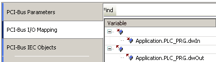
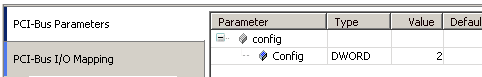
Configure
The configuration parameter is used as a factor, so the formula of the driver looks like:
dwIn := dwOut * Config


Login
When you download this program to your PLC, your PRG should look like this:

I/O driver library
Change the structures
The driver FB is mapping only one input, one output and one configuration parameter. The rest can be defined inside of the structures, named "IoDrvConfigInput", "IoDrvConfigOutput" and "IoDrvConfig". The easiest start is therefore, to change those structures according to your needs. Then you don't need to touch the I/O Driver FB in the folder "Generic".
Note: If you don't need one of the structures, it is more simple to leave them in place, but just remove the parameter from the device description. Because you don't need to change the generic I/O driver FB this way.
Write Driver Code
Write your driver code in the body of "TheFB". This FB is called on every bus cycle, and it contains the structures from the last chapter as inputs and outputs. So the implementation should be pretty much straight forward.
Change Library Details
Double click on "Project Information". There it is mandatory to adapt "Title" and "Namespace". But obviously it makes sense to rework all settings in the dialog.
Add the same information to the "GVL" in the project. There you find some constants, describing the names and module type for the generic I/O driver FB. The module type should follow the rules, described here.
Save
When you have a library open, there is a small button to save and install it in one turn.

Note: I would recommend to open two instances of CODESYS when working with libraries.
Device Description
Change the Types
The Types are defined by default like this:
  <Types namespace="local">
    <StructType name="IoDrvInput">
      <Component identifier="dwIn" type="std:DWORD">
        <Default />
        <VisibleName name="local:Input">Input</VisibleName>
      </Component>
    </StructType>

    <StructType name="IoDrvOutput">
      <Component identifier="dwOut" type="std:DWORD">
        <Default />
        <VisibleName name="local:Output">Output</VisibleName>
      </Component>
    </StructType>

    <StructType name="IoDrvConfig">
      <Component identifier="dwConfig" type="std:DWORD">
        <Default />
        <VisibleName name="local:Config">Config</VisibleName>
      </Component>
    </StructType>

  </Types>
They need to define the exactly same structure as you defined the structures in your library. While this double work might be annoying, the actual process is straight forward.
For some examples check the type examples in the generic driver documentation.
Change the Identification
Change the device identification after the rules, defined here.
Change the Module Type
Change the module type, as described here.
That's it!
After those steps, you should have already a working I/O driver. The main "magic" is done in the I/O driver FB in the subfolder "Generic". Don't worry to change this FB also. The intention of this generic FB is just to make the initial process as easy as possible.