Driver FB
-
Driver Documentation
-
Database
I/O driver
An I/O driver in the world of CODESYS is a piece of software, that abstracts the access to a piece of hardware, which usually provides input data (like temperatures, switches, ...) or drives outputs (analog, digital, PWM, ...).
The way to use those I/Os is usually, to add the modules to the device tree of your CODESYS project, configure them and map the input and output channels to variables i your application.
Function Block
When start writing an I/O driver in IEC, the best way is to start with a function block. The reason is, that it is very easy to pass the input and output values of your hardware to the inputs and outputs of your FB.
Try to keep the interface of the FB as simple as possible, and do all the work, which is necessary to handle the hardware in the main POU of the FB.
So if you for example read a value of a sensor through SPI, name the input of the FB accordingly, and code the SPI access inside of your FB.
I/O driver interface
When you have such an FB, it becomes very straight forward to write an I/O driver frame around that, so that the user can easily add this driver to his project, like he is used to do it with other fieldbusses in CODESYS.
Device Description
A device description is an XML file, which describes the I/O module, so that the user can add it to the device tree in CODESYS. It mainly consists of configuration parameters and I/O channels.
<!-- Configuration parameter -->
        <Parameter ...>
          <Attributes channel="none" ... />
          ...
        </Parameter>
<!-- Input channel -->
        <Parameter ...>
          <Attributes channel="input" ... />
          ...
        </Parameter>
<!-- Output Channel -->
        <Parameter ...>
          <Attributes channel="output" ... />
          ...
        </Parameter>
The purpose of those kinds of parameters is easily explained:
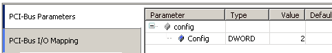
- Configuration Parameters can be used to configure things at compile time (e.g. baudrate, frequency, ...).
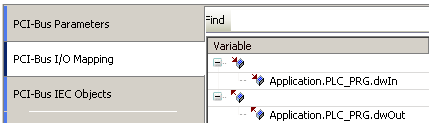
- Input Channels can be used to map an input (e.g. position od rotary encoder, temperarure, ...) to a variable of the application.
- Ourput Channels can be uses to map an output (e.g. relais output, PWM, ...)to a variable of the application.
When you hit "add device" in CODESYS, you get only a list of devices, which are allowed under the selected device. To let CODESYS know which devices are allowed, we have to define so called connectors with interfaces.
<Connector interface="OpenSource:Internal" ...>
The algorithm is simple - you have parent and child connectors, each with 1-n interfaces. Each combination of parent and child, where at least one of the interface names matches is valid, and therefore displayed in the "add device" dialog of CODESYS.